repairing a viper light

ChrisSharman

New member
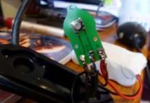
My trusty Viper has packed in - no longer switches on or off.  :cry:

The cable insulation has worn through near the battery, and the brown & blue wires snapped off the switch.
I've shortened the blue wire (which seemed to have suffered where the insulation had worn through), and resoldered blue to the other side of the switch and brown to red.
Seems to charge ok (goes to green light), and the blue flashing indicator registers when the battery's connected to the lamp, but still won't switch on or off.
Switch feels positive, has no visible damage. Picture attached, hopefully.

Any suggestions please?
Thanks, Chris
 

Attachments

  • P1090962.JPG
    P1090962.JPG
    734.1 KB · Views: 252

crickleymal

New member
First things first. Are you sure you got the connections the right way round?
Secondly, do you have a multimeter? If so you can test whether or not the switch is operating. Either with the battery connected, there should be a voltage one side of the switch and not the other until you press the switch when both sides should be at the same voltage. Or without the battery, measure the resistance across the switch, should be high until you press the switch when it should drop to tenths of an ohm.

Those little switches can be a bit temperamental, you could try switch cleaner http://www.maplin.co.uk/p/maplin-switch-cleaner-200ml-n62an but usually that's only a temporary fix. The best bet is to replace the switch.
 

NewStuff

New member
It looks like a 6mm tactile switch, they do fail. Test that with a multimeter, then come back to us if it isn't (I'm betting it is). Assuming it is, they're pennies, literally, under a quid each. Search for 6mm PCB tactile switch on fleabay or similar.
 

ChrisSharman

New member
Thanks for that. The switch is working correctly, according to my multimeter.
I'm not certain which way round the blue and brown wires should be: they were both snapped off.
However, the terminals are marked +, -, and MS.
The switch is between - & MS.
The battery (red & black) is connected to + & - respectively.
The external cable has brown, blue, and black and the black was connected to - (as the battery black).
I can't trace inside the connector, but when I connect up the charger, it seems to recognise the presence of a battery, and after a while thinks it's charged it. I doubt it would work that well if it wasn't connected to the battery directly (since the switch is always off unless it's held down).
So blue to MS (switch) and brown to + (battery red) seems like the only reasonable way to connect them.
I'm reluctant to just try swapping them over as I think polarity matters and I don't want to damage anything.
I think my next task is to try opening the headset, to see whether the switch signal reaches there.
That appears to involve removing 6 year old mud encrusted corroded screws from the lens.


Alex

Well-known member
My rude nora is also buggered Sharman, it seems I may have yanked it too hard. That's two club members with no good lights no wonder trips have been light recently.
 

Ian Ball

Well-known member
What does MS stand for?  If Master Switch would it suggest a second switch somewhere? Possible guard against battery drain when off? Where is a viper light manufactured?


ChrisSharman

New member
Don't know what MS stands for - there's no other switch I'm aware of - the battery is joined to the headset or the charger with an inline connector.
Viper I think used to make caving & bike lights - a little cheaper than scurion. I believe the owner retired.
There's very little in the battery case: seems to be just the lithium battery and the board pictured.
The push switch switches it on, cycles it through 4 brightness levels, and (longer push) switches it off.
Disconnecting the battery and headset when not in use is recommended, and there's a blue indicator lamp which flashes slowly when the lamp's off if it's still connected.
I managed to remove 5 of the 6 screws in the lens, but the 6th is buggered.
Running out of ideas - starting to look like I need a new light.
 

NewStuff

New member
Chuck some Plusgas on the 6th screw. Works miracles on stuck/rusted screws that stuff.

Without a schematic, or seeing the circuit to decipher a schematic, it's purely guesswork. If the repaired solder connections are as pictured, I'd suggest cleaning them off and re-flowing them with some flux, if nothing else, it will eliminate that as a problem. Using leaded 60/40 is usually easier to work with.

Both items readily available on ebay.
 

royfellows

Well-known member
You have a multimeter. Have you checked that there is definitely no output from the battery pack with its integral drive electronics?

The lamp appears to have 3 series LEDS, one could have failed.


ChrisSharman

New member
There definitely is output according to the multimeter.
The charger is definitely behaving as if it sees the battery.
The lamp flashes its blue LED as it's supposed to when the battery is connected.
It initially failed ON: the lamp was on but I couldn't alter the brightness or switch it off.
Next time the helmet banged into something it went out, and hasn't been on since.
So it appears it's the switch output not being received by the lamp (the multimeter confirms the switch is working at its pcb).
Will try some plusgas, thanks.
 

royfellows

Well-known member
I would really like to try and help but there is a complete absence of any information on the web about these lamps. It appears to have 3 LEDs which I think must be series wired, battery case looks about 3 cell size. If so it was a lamp before its time as to best of my knowledge I am only person series wiring multiple LEDs to match input voltage from series cells. The emitters, I believe are XR-E possibly now considered obsolete.
I am doing some experimenting at the moment and it seems 12V (11.2 nominal) is a magic number for a lamp.
On face of it, all electronics are in the battery pack, so I would again expect the lamp to only house the LEDs plus battery voltage indicator mounted on a plain board. All this is guesswork.

The fact that the main LEDs illuminated at one time suggests that they are all working, so we are back to the power pack and its electronics. However, with nothing much to loose I would try applying a gradually increasing voltage from a lab PSU direst to the lamp and see if the main LEDs light up. A techy friend may have a lab power supply unit for this.

If you are ever around Cannock pop in here with it.
 

ChrisSharman

New member
Well, the switch still isn't working - but it's on all the time again now (when the battery's connected).
I've got all 6 screws out of the headset, but I still can't prise the polycarbonate lens out.
By a process of elimination, I think the fault must lie in the headset or its cable or in the blue wire from the switch.
There I'm stuck - the connectors are too small for me to tackle with a multimeter, and to replace the wires requires opening the headset. Don't think I can afford to shorten the wires any more, either - I've already sacrificed about 2" to remove the worn part coming out of the battery box.
Will keep trying - thanks for all the help and suggestions.
 

royfellows

Well-known member
ChrisSharman said:
By a process of elimination, I think the fault must lie in the headset or its cable ......

Cable is interesting. I have had cable issues on my lamps and now fit different glands, the glands were the source of the issue.
If the cable is a flexible rubber the inner metal strands can fail through metal fatigue in the vicinity of the gland. Try switching the lamp on and moving the cable about.
 
Top