

AlexR
Active member
:idea:10 ways to break your Scurion, number 6 will surprise you! :idea:
Crawling up the walls in lockdown? Need some excitement in your life? Got an old Scurion 700 basic and want more bang for you buck?
Then this is for you. Written like a manual, but don't come blaming me after you've plunged your soldering iron straight into the LED driver and knackered your light. I'm very new to electronics, having picked it up as a hobby in lockdown. Prior to messing with the Scurion I de- and then re-soldered some SMD (surface mount device) components from knackered PCBs to get a feel for it.
How easy it is to carry out the upgrade? Pretty relative, someone like Biff or Roy (Fellows) could do it before breakfast; I found it a bit daunting but fairly easy in the end.
Why bother
The original Basic (bought from Tony in 2013) is equipped with 2 Cree XP-G LEDs. Technology has moved on somewhat and the current equivalent is the XP-G3. If Rolf used the highest binned LED, which I assume, you're getting 348 lm at 1 A (148 lm/W). This is the current they appear to be supplied with in the highest mode.
XP-G3 LEDs are available for little cost even in their highest bin (S5, 5000K, not fussed about CRI), giving me 470 lm at 1 A (190 lm/W).
More lumen at a lower power consumption.
The XP-G3 could be driven harder without loosing much in terms of efficiency (1.5A would still be conservative with as good a heatsink as the Scurion provides), but this requires messing with the driver, i.e. more ability and knowledge than I have.
NB: You can't just go and take any old Cree or other LED, the XP-G3 works very well in this setup because it is dimensionally identical to its predecessor.
The "better" Scurions utilise XM-L emitters, an analogous upgrade can be carried out for those.
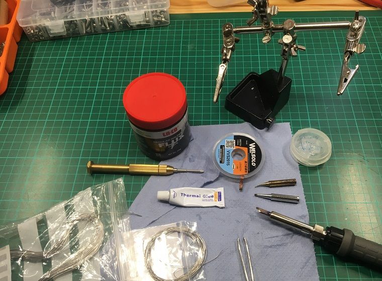
What you'll need
- The ability to hold a soldering iron the right way around
- A fairly chunky soldering iron tip if using a variable temperature soldering iron or a hefty thermally balanced iron (You'll be soldering on a heat sink)
- SMD solder wire or SMD paste and standard solder, extra flux helps. All of the extra juicy, ~60/40 lead-containing variety, not the lame industry-approved lead free one
-A reflow oven
- More realistically, a small hot air gun or skillet to remove & attach the LED (google SMD removal for info)
- de-soldering aid (I used a copper wick)
- 2 Cree XP-G3 LEDs from a reputable seller. If photography is important, choose a high CRI at the price of a lower bin (fewer lm). They cost next to nothing, and I found it reassuring to have more than 2 in case I fried one. (In my case they came from RS Components)
- silicone-based thermal adhesive
- T10 bit to remove the window, Pz for the internal bolts
- tweezers
- third hand (or any jig to hold items whilst soldering)
- a digital multi meter helps as a sanity check
Ready? Let's go!
The upgrade
Removed the window
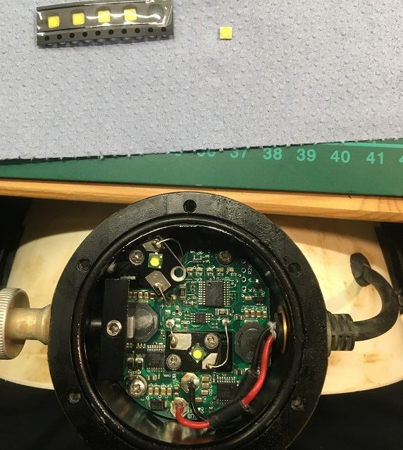
Removing the flood chip: I took out the bolt and lifted the chip. There is adhesive connecting it to the lamp body, which in my case didn't actually stick at all. Removed old adhesive with isopropyl alcohol (alternative: ethanol, or failing that your mate's favourite whisky).
De-soldered the wire. The heat sink does its job well, and I found a temperature of 400?C was necessary to melt the solder in a timely fashion. I opted for completely removing the old solder from the chip as I suspect it's of the lead-free variety, which just isn't as juicy as the braincell-killing lead containing one.
Removed the LED with a hot air gun (other methods possible). Then cleaned up the contacts with flux and solder wick.
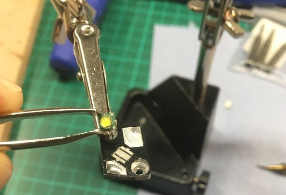
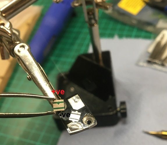
Installed the new LED. LEDs are diodes, and as such polarity sensitive. The XP-G3 has a clearly visible nook underneath it which denotes the +ve side (the triangle is pointing from +ve to -ve). I put the tiniest piece of SMD solder wire on the anode and cathode, and a slightly larger bit on the middle (thermal path), together with a more liberal amount of flux. Hot air until molten, place LED on top, left heat on for another second or so, and you're done. The LED aligns itself, if you've used too much solder you might want to apply some gentle pressure whilst still hot to squeeze out the excess.
Reinstalled the chip by first soldering the wires back on, then put thermally conductive adhesive on the pillar the chip sits on, and finally bolted it down. Do not bolt it down first, this would make soldering impossible or very hard (I left it unattached and glued it on the same time I did the spot).
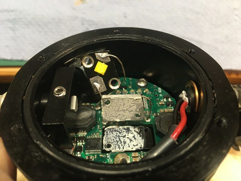
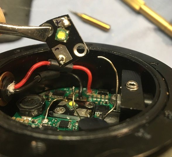
Flood done, spot chip lifted and adhesive visible
Repeat the process with the spot LED. This is more fiddly to get to and solder, so it's best to do flood first.
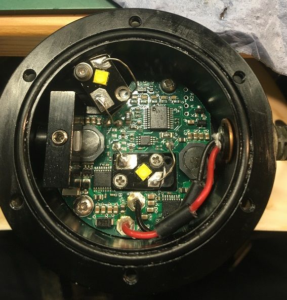
Close everything back up, and you're done!
As an aside, one of the bolts holding down the LED heatsink was fairly chewed even before I removed it, so I replaced it. They are 4 mm M2 countersunk Pz, the closest I had was a hex socket equivalent. No comments about the proximity of the washer to the contact please
If all this sounds a bit much to you, Rolf (Scurion) will also upgrade your light. As of pre-Brexit, the update of a 700 basic to a 900 will set you back ?180, or ?220 for a 1500 plus ?20 postage. You'll then have someone who knows what they're doing opening your treasured head torch. LEDs don't like being too hot, and there definitely is a danger of damaging it in the process.
Although the initial price of a Scurion is eye watering, mine has worked out as ?43 per year so far, and seen 8 years of pretty abusive caving and digging. The plastic battery case has packed it in, probably because I use it as a handle when the helmet has to come off in tight passages.
PS:
I guess it's pretty obvious, but just to cover myself: This level of fettling will of course void your warranty!
Crawling up the walls in lockdown? Need some excitement in your life? Got an old Scurion 700 basic and want more bang for you buck?
Then this is for you. Written like a manual, but don't come blaming me after you've plunged your soldering iron straight into the LED driver and knackered your light. I'm very new to electronics, having picked it up as a hobby in lockdown. Prior to messing with the Scurion I de- and then re-soldered some SMD (surface mount device) components from knackered PCBs to get a feel for it.
How easy it is to carry out the upgrade? Pretty relative, someone like Biff or Roy (Fellows) could do it before breakfast; I found it a bit daunting but fairly easy in the end.
Why bother
The original Basic (bought from Tony in 2013) is equipped with 2 Cree XP-G LEDs. Technology has moved on somewhat and the current equivalent is the XP-G3. If Rolf used the highest binned LED, which I assume, you're getting 348 lm at 1 A (148 lm/W). This is the current they appear to be supplied with in the highest mode.
XP-G3 LEDs are available for little cost even in their highest bin (S5, 5000K, not fussed about CRI), giving me 470 lm at 1 A (190 lm/W).
More lumen at a lower power consumption.
The XP-G3 could be driven harder without loosing much in terms of efficiency (1.5A would still be conservative with as good a heatsink as the Scurion provides), but this requires messing with the driver, i.e. more ability and knowledge than I have.
NB: You can't just go and take any old Cree or other LED, the XP-G3 works very well in this setup because it is dimensionally identical to its predecessor.
The "better" Scurions utilise XM-L emitters, an analogous upgrade can be carried out for those.
What you'll need
- The ability to hold a soldering iron the right way around
- A fairly chunky soldering iron tip if using a variable temperature soldering iron or a hefty thermally balanced iron (You'll be soldering on a heat sink)
- SMD solder wire or SMD paste and standard solder, extra flux helps. All of the extra juicy, ~60/40 lead-containing variety, not the lame industry-approved lead free one
-
- More realistically, a small hot air gun or skillet to remove & attach the LED (google SMD removal for info)
- de-soldering aid (I used a copper wick)
- 2 Cree XP-G3 LEDs from a reputable seller. If photography is important, choose a high CRI at the price of a lower bin (fewer lm). They cost next to nothing, and I found it reassuring to have more than 2 in case I fried one. (In my case they came from RS Components)
- silicone-based thermal adhesive
- T10 bit to remove the window, Pz for the internal bolts
- tweezers
- third hand (or any jig to hold items whilst soldering)
- a digital multi meter helps as a sanity check
Ready? Let's go!
The upgrade
Removed the window
Removing the flood chip: I took out the bolt and lifted the chip. There is adhesive connecting it to the lamp body, which in my case didn't actually stick at all. Removed old adhesive with isopropyl alcohol (alternative: ethanol, or failing that your mate's favourite whisky).
De-soldered the wire. The heat sink does its job well, and I found a temperature of 400?C was necessary to melt the solder in a timely fashion. I opted for completely removing the old solder from the chip as I suspect it's of the lead-free variety, which just isn't as juicy as the braincell-killing lead containing one.
Removed the LED with a hot air gun (other methods possible). Then cleaned up the contacts with flux and solder wick.
Installed the new LED. LEDs are diodes, and as such polarity sensitive. The XP-G3 has a clearly visible nook underneath it which denotes the +ve side (the triangle is pointing from +ve to -ve). I put the tiniest piece of SMD solder wire on the anode and cathode, and a slightly larger bit on the middle (thermal path), together with a more liberal amount of flux. Hot air until molten, place LED on top, left heat on for another second or so, and you're done. The LED aligns itself, if you've used too much solder you might want to apply some gentle pressure whilst still hot to squeeze out the excess.
Reinstalled the chip by first soldering the wires back on, then put thermally conductive adhesive on the pillar the chip sits on, and finally bolted it down. Do not bolt it down first, this would make soldering impossible or very hard (I left it unattached and glued it on the same time I did the spot).
Flood done, spot chip lifted and adhesive visible
Repeat the process with the spot LED. This is more fiddly to get to and solder, so it's best to do flood first.
Close everything back up, and you're done!
As an aside, one of the bolts holding down the LED heatsink was fairly chewed even before I removed it, so I replaced it. They are 4 mm M2 countersunk Pz, the closest I had was a hex socket equivalent. No comments about the proximity of the washer to the contact please
If all this sounds a bit much to you, Rolf (Scurion) will also upgrade your light. As of pre-Brexit, the update of a 700 basic to a 900 will set you back ?180, or ?220 for a 1500 plus ?20 postage. You'll then have someone who knows what they're doing opening your treasured head torch. LEDs don't like being too hot, and there definitely is a danger of damaging it in the process.
Although the initial price of a Scurion is eye watering, mine has worked out as ?43 per year so far, and seen 8 years of pretty abusive caving and digging. The plastic battery case has packed it in, probably because I use it as a handle when the helmet has to come off in tight passages.
PS:
I guess it's pretty obvious, but just to cover myself: This level of fettling will of course void your warranty!