Diving light LED conversion - for Peter Hall

royfellows

Well-known member
Peter has sent me a Halcyon diving light, as Peter describes it,  "that were clearly very good bits of kit in their day, but the technology has moved on a bit since.

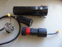
The lights include a depth rated battery canister capable of holding (I think) 21 18650 cells and a nicely made, depth rated light unit on a wire (see attached).

The original lamp uses 21 NiMH cells and an "HID" bulb, which is both expensive and very fragile (so not particularly suitable for UK sump diving)."

The mission is to convert this, and possibly another to modern high brightness LED - Lithium Ion battery powered

the lights appear to be extremely robust and well made, however a drawback is the 35mm internal diameter of the lamp, obviously only room of one LED with a decent beam reflector, and the rather oversize battery canister.

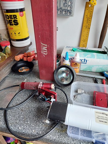
After some consideration I decided to go for beam quality using a large 35mm LED reflector over a Cree XHP 35 quad die emitter. This would be overdriven to 1.5 amps with a forward voltage of a tad over 12V. My lab experimentation has confirmed that this level of overdrive ( stated max 1050 mA) is safe and reliable subject to good heat dissipation, the latter being achieved by mounting on a copper base. This has been the design for my X16 caplamp, my own has been in reliable use now for 3 years. However the X16 has 2 of these.

As such, the electronics will be as used in the X16 including the battery charge control with its pretty gallium nitride green charge indicator.
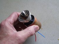
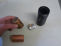
The internal diameter of the lamp is good as 35mm copper pipe is readily obtainable, and highly suited to the LED module.
I will be describing the conversion blow by blow as it progresses, I know we have at least one other diver on here!

Picture shows lamp body and base module made from a section of the copper peipe. The reflector is from KD Hong Kong, they have possibly best selection on the web.
 

Attachments

  • base_assy.JPG
    base_assy.JPG
    7.2 MB · Views: 183

PeteHall

Moderator
Glad it's providing you some interest Roy and thanks for sharing details of the conversion.  (y)

Look forward to seeing it progress and obviously trying it out once it's done.  :)
 

royfellows

Well-known member
I have finished the light module and will now be moving to the batteries. The compartment is a bit on the big side and would hold 12 18650 cells, we are going to use 8.
The module has a single Cree XHP 35, the driver is an ?off the shelf? from Kaidomain.

http://kaidomain.com/Flashlight-DIY-and-Tools/Flashlight-Drivers/S025219-FX-3XT6-25mm-2A-5_5V-16V-4-Groups-3-to-5-Mode-Driver-Circuit-Board-for-3-x-Cree-XM-L

It?s a fairly straightforward buck driver and by making a solder bridge can be set to three different mode programs, I select the three without silly flashes.

As it comes the output is far too high at 2 amps for this purpose, I remove the 0.1 ohm sense resistor and replace it with a 1 ohm and a 0.18 ohm, this gives a max output of exactly 1.5 amps. I used these in my custom torch that has been giving good service for a few years now.

It?s also necessary to remove the reverse polarity protection diode, unnecessary in anything with fixed batty cells, and a terrible waster of efficiency. It runs now at over 80% which is OK.

The IC chip is interesting as it?s a programmable LED driver switching an external MOSFET, with flyback diode etc. It?s had its part no sanded off, seen it in other Chinese drivers, obviously an overproduction of something for Western companies. I would love to ID it.
It has a lot of firmware for single chip but no mode memory, so will always turn on at the lowest setting. They usually use an EEPROM, or a chip with this feature, for a mode memory, (Electronically erasable program, read only memory). ROM is the mode firmware, the EEP is the mode memory which stays current even if you switch off and take the battery off. Next day, it comes on the last setting, but is reprogrammed when you switch modes. These circuits need a lot of external components. The chip is a low voltage typically 2.5V so needs a voltage regulator; the EEPROM also needs to work through an LED driver, however this is a common design.

I am still testing my own F_Tech driver, which would have been an alternative, but its advantages would be negated somewhat by the large battery capacity of this project.
 

Attachments

  • module.JPG
    module.JPG
    7.1 MB · Views: 114

Cantclimbtom

Well-known member
Out of sheer nosiness, how long would that run for?
Tempted to look at 8 * 2.5ah  and use 1.5a draw and divide the two (40/3 ~13), but due to low-voltage cut off and whatever I'm not sure that's reliable. Do you have a rule of thumb / fudge factor for estimating these things please
 

royfellows

Well-known member
The cells are my standard Sanyo NCR 18650GA 3.5 Ah @ nominal 3.6V.

Obviously, the burn time will depend on the output mode, there are three.
The battery capacity is best converted to watt hours, so we have 3.6 X 3.5 = 12.6 Wh per cell. 12.6 X 8(cells)  = 100.8 watt hours at the nominal voltage. Nominal voltage is a good ?centre line? and gives reasonable accuracy in estimations of burn time, see my previous estimate of the F_Tech driver in that thread.

Now current in will be appreciably less than current out with any reasonable switch mode buck driver. However at an input voltage near to the Vf of the LED or LEDs this will change. The XHP 35 is a quad die, so in effect, 4S LEDs in one. And the input voltage of 13.8V is only slightly more than the forward voltage of the LED, in this case about 12.8V.

As a point of interest, it can often be difficult measuring the voltage out with a meter, best at least checking against the data sheet. In this case as we are overdriving, I have had to extrapolate the data sheet.

Anyway, battery hit in watts
Low mode 0.552
Mid 4.83
High 21.25
So, low mode 182 hours, mid 20.86 hours, high mode 4.74 hours.
 

ChrisJC

Well-known member
royfellows said:
The IC chip is interesting as it?s a programmable LED driver switching an external MOSFET, with flyback diode etc. It?s had its part no sanded off, seen it in other Chinese drivers, obviously an overproduction of something for Western companies. I would love to ID it.

It is probably a Chinese knock-off of a Western part. You might well find that if you could ID it, the datasheet would have diagrams blatantly copied from the original Western datasheet!

Chris.
 

royfellows

Well-known member
Hi Chris, what I am basically saying, but if you can get a Chinese data sheet for a Chinese rip off part you would indeed be lucky. I would go for the western data sheet.

I have seen the same chip in other driver modules, I call it "The chip with no name"
:LOL:
 

royfellows

Well-known member
I have finally completed Peters lamp. The battery module is 2 parallel by 4 serial Sanyo NCR 1865 GA cells giving nominal voltage of 13.8V and have same management module as my X16 lamp.
It really does like something you would fire at a Russian tank, but is designed to fit neatly into the waterproof container.

I have kept charging simple by a dedicated 16.8V charger, rather than the X16 ?light show?.

If there is something here to be learnt, its how now obsolete bulb and NiCad dive lights can be purchase cheaply and then converted into state of the art at small cost. Obviously, biggest single component cost here is battery cells.
 

Attachments

  • battery.JPG
    battery.JPG
    7 MB · Views: 113

Pitlamp

Well-known member
Very impressive Roy; well done.  :clap:

I see Pete Hall has "liked" it. I bet he does, 'an all! 
 

PeteHall

Moderator
I think I shall certainly like it!  (y)

Looking forward to trying it out too.  If If arrives in time, I'm in the Dales this weekend and might give it a test in Keld, otherwise it will probably get a Wookey christening in a few weeks.  :)
 

amw

Member
There could be an issue with heat sinking and dissipation due to the size and shape of the lamp.

I am replacing the headset with another old one from a HID lamp I no longer use. Driver wise, I am, looking at a TPS92633-Q1 as I have  a few free samples :) .

Sue's not letting you do that in the new kitchen is she
No chance just the photo out in the workshop for the work.
 
Top