LIDAR Cave Scanning

Andy Farrant

Active member
I can think of lots of useful applications for this type of cave survey, both for geological and archaeological applications, although I agree with nobrotson in that it probably won't be a substitute for traditional cave surveys just yet. But most cave surveys don't give you much information on passage shape or geometry, nor do they give any indication if a passage is say vadose or phreatic. This is where lidar or photogrammetry has real advantages.
 

Chocolate fireguard

Active member
If I have understood this properly it's about using the inertial system available in a phone to log position and lidar to photograph the cave as you move through it.
Inertial systems need regular checking (Galileo, gps etc) which is obviously not possible underground, and without it errors go uncorrected.
It seems that the best accelerometers are accurate to about 5 micro g, which is about 0.00005 m/s2, so taking that as the minimum error, and using s = 0.5 at2, after 100 seconds the position will be wrong by 0.25 m. The dependence on time squared means that after about 3 minutes it will be out by a whole metre.
I imagine the drift that Rostam mentioned was due to this, but I may have got it wrong completely.
It all sounds very interesting though, and I assume there is one of those app things I can downshift to my Nokia 2310 so I can have a play?
 

Steve Clark

Well-known member
Interesting latest post from the Nutlar project about converting 3d photogrammetry into a ortho plan.

https://www.facebook.com/GUEProjectNuttlar/
 
Chocolate fireguard said:
If I have understood this properly it's about using the inertial system available in a phone to log position and lidar to photograph the cave as you move through it.
Inertial systems need regular checking (Galileo, gps etc) which is obviously not possible underground, and without it errors go uncorrected.
It seems that the best accelerometers are accurate to about 5 micro g, which is about 0.00005 m/s2, so taking that as the minimum error, and using s = 0.5 at2, after 100 seconds the position will be wrong by 0.25 m. The dependence on time squared means that after about 3 minutes it will be out by a whole metre.
I imagine the drift that Rostam mentioned was due to this, but I may have got it wrong completely.
It all sounds very interesting though, and I assume there is one of those app things I can downshift to my Nokia 2310 so I can have a play?
Its not back fixing using GPS thats too inaccurate for the measurements.
code wise some details here:
https://developer.apple.com/documentation/arkit/content_anchors/visualizing_and_interacting_with_a_reconstructed_scene
They also recommend a good light

Light the object with an illuminance of 250 to 400 lux, and ensure that it?s well-lit from all sides.

Provide a light temperature of around ~6500 Kelvin (D65)??similar with daylight. Avoid warm or any other colored light sources.

https://developer.apple.com/documentation/arkit/content_anchors/scanning_and_detecting_3d_objects


Chocolate fireguard

Active member
I am not sure what you mean when you say "it's not back fixing using GPS that's too inaccurate for the measurements". What I said was that inertial systems have to be corrected regularly, and GPS is one of the ways of doing it, but obviously not available underground.

The expensive gizmo from Leica that Leclused mentions is advertised as being suitable for use underground. It is implied - but not specifically stated - that it's inertial tracking system is corrected by comparing successive pictures to determine the scanner's movement.


Steve Clark

Well-known member
CJ said:
I've just been messing around with some scans and I see the issues with deciding where to slice for the purposes of a 2D survey. How is this issue solved for traditional surveying methods? Am I aiming to convey the "floor" of a passage, or to provide a general gist of the passage? Or showing the tightest constriction? e.g. an unusual hourglass shaped passage: how would that look on a top down 2D survey? My first thought would be to capture the dimensions of the ground and then provide a cross-sectional view for that part?

This is the crux of it! As noted in the other posts, there's (currently) a big difference between a 3d scan/survey/model and a functional map/survey that's useful for use by cavers or divers. It's down to the interpretation of the cartographer as to how to represent the cave, such that's it's accurate but also conveys the detail of the passage to make it most useful.

For walking & crawling about, you can put loads of referenced cross-sections on (e.g. like the RRCPC Lancaster hole survey), which is great for completeness, but in practical terms most people just use the plan and the passage width/colour, combined with 'P5' / 'C3' / 'tight' symbols are the most useful.

Similarly, for vertical stuff, the compass direction is less important, hence the rigging type topo is really easy to follow and can be quite schematic without being a problem. A plan of Rowten or Simpsons is very difficult to follow for example.

For diving, you need depths. The elevation profile is essential for planning and the plan is also key for finding gaps/leads. Important to label actual sketched wall/ceiling and 'presumed' wall / ceiling. Also, the dive line in a submerged cave is often in a completely different place to where you would walk or rig through the same cave. It will often be nowhere near the 'floor', which may be a massive sloping mud bank. It's often tricky to estimate LRUD (left, right, up, down) when you can't see the walls, or the cave exists beyond where you can fit. You can often see an air surface but not actually get up to it (at least for us fat, back-mounted folks)

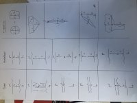
Some examples below. The interesting one is the diagonal rift *. The passage is actually really 'wide' but it would be wrong to represent it like that on the plan. It would 'feel' narrow but also high passing through it. You can also use floor and ceiling step symbols to deal with classic streamway shapes.


Attachments

  • 2022-01-18 14.35.59.jpg
    2022-01-18 14.35.59.jpg
    4 MB · Views: 121

Bob Mehew

Well-known member
I presume the capturing device uses an Inertial Measurement Unit (IMU) to determine its movement and hence produce a set of points on which the images can be located. Electronic IMUs work on using accelerometers, gyroscopes and magnetometers.  Whilst I vaguely understand the principles of the sensors, what is not clear to me is how the output data of the sensors is used to compute the distance of movement and how the three sensors are used to self correct the overall measurement.  Can any one point to a good read? / explain it?  Apologies for going off at a tangent.
 
Chocolate fireguard said:
I am not sure what you mean when you say "it's not back fixing using GPS that's too inaccurate for the measurements". What I said was that inertial systems have to be corrected regularly, and GPS is one of the ways of doing it, but obviously not available underground.

The expensive gizmo from Leica that Leclused mentions is advertised as being suitable for use underground. It is implied - but not specifically stated - that it's inertial tracking system is corrected by comparing successive pictures to determine the scanner's movement.

Sorry I was meaning was that GPS is never an option for corrections for an IMU on a phone. The IMU is combined with photographic and/or scanning to correct the IMU errors.


Steve Clark

Well-known member
Bob Mehew said:
I presume the capturing device uses an Inertial Measurement Unit (IMU) to determine its movement and hence produce a set of points on which the images can be located. Electronic IMUs work on using accelerometers, gyroscopes and magnetometers.  Whilst I vaguely understand the principles of the sensors, what is not clear to me is how the output data of the sensors is used to compute the distance of movement and how the three sensors are used to self correct the overall measurement.  Can any one point to a good read? / explain it?  Apologies for going off at a tangent.

This is an old video now, but it rapidly explains the problems with trying to combine sensor outputs from accelerometers, magnetometers & gyros in handheld devices. The difficulty is integrating gyro (velocity) & double-integrating acceleration to get the distance/displacement that you want. Very difficult to separate acceleration due to actual movement & apparent acceleration due to gravity. Results in large drift which can swamp all other data.

https://www.youtube.com/watch?v=C7JQ7Rpwn2k
 

Chocolate fireguard

Active member
mountainpenguin said:
Chocolate fireguard said:
I am not sure what you mean when you say "it's not back fixing using GPS that's too inaccurate for the measurements". What I said was that inertial systems have to be corrected regularly, and GPS is one of the ways of doing it, but obviously not available underground.

The expensive gizmo from Leica that Leclused mentions is advertised as being suitable for use underground. It is implied - but not specifically stated - that it's inertial tracking system is corrected by comparing successive pictures to determine the scanner's movement.

Sorry I was meaning was that GPS is never an option for corrections for an IMU on a phone. The IMU is combined with photographic and/or scanning to correct the IMU errors.
I see, thank you.
That video brings out very well the problems with using accelerometers, gyroscopes and magnetometers to give something that GPS does far better anyway.
The huge amount of error shown in the bit about double integrating a noisy accelerometer signal to get displacement would surely mean that any attempt to use that without some form of correction in a cave survey would produce errors that couldn't really be described as "drift", as Rostam did!
So presumably his (and the OPs) phone would have used some form of photographic correction?
 
All inertial systems require some form of aiding to correct for drift. Oilwell survey tools used cable length, underwater devices can use depth and periodic "down mode align" or "zero velocity update" stops, aircraft systems can use GPS, radar, altimeter, and known waypoints. Many of these devices are based on quartz flexure accelerometers and ring laser gyros, which are more accurate than the MEMS sensors in phones.
However, I can't help wondering whether a LIDAR equipped system might be able to make use of the stationary property of cave wall features (or fixed artificial features), in order to generate updates continuously.
 

Steve Clark

Well-known member
andybrooks said:
However, I can't help wondering whether a LIDAR equipped system might be able to make use of the stationary property of cave wall features (or fixed artificial features), in order to generate updates continuously.

This TED talk from Bill Stone features an autonomous drone that does simultaneous LIDAR location & mapping. Pretty sci-fi, but the idea is sound. Uses the LIDAR to build a model, then uses the model as fixed points to navigate from.

Skip to about 8min in :

https://www.ted.com/talks/bill_stone_inside_the_world_s_deepest_caves?language=en
 

andrewmcleod

Well-known member
andybrooks said:
However, I can't help wondering whether a LIDAR equipped system might be able to make use of the stationary property of cave wall features (or fixed artificial features), in order to generate updates continuously.

It's called SLAM (simultaneous localization and mapping), no inertial measurement required, and it's not a new thing. Mad Phil did a good talk at Hidden Earth a few years ago. The LIDAR system can track its surroundings as you walk around and use that to track its current position. It's still susceptible to drift; the example he gave was that when he went into a mined section in a Chinese show cave (with a consistent square concrete cross-section) the system lost track of where it was and the mined section appeared a lot shorter than it really was.
 

roo.walters.4

New member
I guess having LiDAR scanned a lot of caves and cave passage i guess i can comment. Like all surveying - LiDAR accuracy is improved if a closed-loop can be arranged. Whether or not that is via two entrances and across the surface, or down separate sides of a large passage or chamber, any loop helps. With the finest terrestrial LiDAR available, i get a drift of between 1m and 2m per km without any other corrections or loops. It does depend on the complexity of the passage, as stated before, uniform subjects such as tunnels are by far the worst. So yes - drift is a problem with LiDAR surveying in caves, tackled by closed-loops, GNSS reference points, subsurface position location (with GNSS on the surface) and even ?dead reckoning.

Creating 2D maps from LiDAR is also an issue. The main one being is that the LiDAR captures everything. The true shape of a cave passage is often not the one percieved as the caver navigates a passage and they don?t notice every boulder, nook and crevise. So the skill of the caving cartographer remains - interpreting what they can see whilst surveying or studying LiDAR scans to create a map that fits the purpose to what it is intended.

There is no doubt that LiDAR has a great deal to offer, but it has not replaced our Distos and pocketPCs - yet. However, I do think that SLAM will in time yield a product that will, and that day is soon. The price may still be out of reach for most cavers.
 

Rob

Well-known member
Excellent input Roo.  (y)  I'd add that the price will be very reachable for most cavers as soon as it is in-phone....

Another closely related topic is how our use of 2D maps may evolve over the next few decades. We all find them useful and even enjoyable to look at, but i can foresee a time when we use 3D surveys more. I already do with survex files, and a point cloud would be even better.

Nowadays I always have a phone with me in caves, so using 3D data to navigate or study a cave feels like an obvious step. Even better is a 3D cave survey through a VR headset, but that's a different story! :eek:

But i do link back to the main hurdle here being the processing of the data, a task not seamlessly developed yet. But the way phones are progressing, i bet it's not far away.
 
Top