Measuring stream flow

Kenilworth

New member
Does anyone have a technique for masuring stream flow that is accessible to an ignorant layperson? I understand what data need to be collected (velocity over a cross section) but the various ways of collecting such seem impractical or difficult to accomplish in a remote in-cave setting. I do not need super high precision, I'm only making comparisons for exploratory purposes.

Thank you
 

PeteHall

Moderator
A V-notch wier is a very effective way to measure flow. How practical that would be in a cave,  I don't know,  but in a smaller stream could probably be improvised with an appropriately shaped board and some sand bags
 

Pitlamp

Well-known member
The traditional "poo-stick" float, favoured by geography teachers, is apparently a small orange.

Cross sectional area can be estimated with a tape measure - measuring depth at intervals at 90 degrees to the stream to produce an approximate cross section. You then just need a stop watch and a calculator.
 

Boy Engineer

Active member
Pitlamp said:
The traditional "poo-stick" float, favoured by geography teachers, is apparently a small orange.

Not only is it favoured by geography teachers, it is actually officially sanctioned by the mandarins in Whitehall. Apparently it?s more accurate if you use a naval orange*.


* don?t write in. I know, but the joke works better misspelt.
 
  • Like
Reactions: CJ

pwhole

Well-known member
Someone gave me a box of about a hundred orange 'ping pong' balls for doing this sort of thing - it's unlikely I'll ever use them, but I'll hang onto them rather than throw them away at least. If anyone wants them, either to measure flow or to make some exotic earrings (maybe even a Carmen Miranda headpiece), let me know. I doubt they'd stand up to playing actual ping-pong.
 

Kenilworth

New member
Pitlamp said:
The traditional "poo-stick" float, favoured by geography teachers, is apparently a small orange.

Cross sectional area can be estimated with a tape measure - measuring depth at intervals at 90 degrees to the stream to produce an approximate cross section. You then just need a stop watch and a calculator.

I don't think my stream will float an orange as it's not deep enough. Is there a reason why an orange is favored, and will a smaller, higher riding float do the job?
 

Stuart France

Active member
My suggestion is record the water depth in a river passage which has a straightforward profile, like a flat bottom river and which has near vertical walls.  Don't bother with V-notch dams.  In our case we had a 2m wide cave river on a shallow gradient with near vertical walls.  There are formulae to convert this to flow rate:

https://www.lmnoeng.com/flowrate.php

We did exactly this job at a show cave business 15 years ago which was contemplating investing in generator plant to produce electricity for itself and/or to sell excess to the grid out of season (which is when most of it would be produced in the winter).  We did a return on investment calculation.

We also compared our flow rates based on underground river depth recorded hourly by a logger with the govt Environment Agency's occasional experiments on a surface part of the same river and obtained a surprisingly good correlation, except of course that we had near continuous readings over a year and they had maybe one dip a month back in those days.  The EA would have measured the flow rate with a turbine based sensor on the end of broomstick poked into the river in that era.  Anyway the business did invest in plant and has been happy with the outcome which was in line with predictions.

If you don't have a depth logger or a turbine type of flow rate sensor, then just use a dipstick for the water depth then plug it into the LMNO engineering model to get the flow rate.


Kenilworth

New member
Stuart France said:
My suggestion is record the water depth in a river passage which has a straightforward profile, like a flat bottom river and which has near vertical walls.  Don't bother with V-notch dams.  In our case we had a 2m wide cave river on a shallow gradient with near vertical walls.  There are formulae to convert this to flow rate:

https://www.lmnoeng.com/flowrate.php

We did exactly this job at a show cave business 15 years ago which was contemplating investing in generator plant to produce electricity for itself and/or to sell excess to the grid out of season (which is when most of it would be produced in the winter).  We did a return on investment calculation.

We also compared our flow rates based on underground river depth recorded hourly by a logger with the govt Environment Agency's occasional experiments on a surface part of the same river and obtained a surprisingly good correlation, except of course that we had near continuous readings over a year and they had maybe one dip a month back in those days.  The EA would have measured the flow rate with a turbine based sensor on the end of broomstick poked into the river in that era.  Anyway the business did invest in plant and has been happy with the outcome which was in line with predictions.

If you don't have a depth logger or a turbine type of flow rate sensor, then just use a dipstick for the water depth then plug it into the LMNO engineering model to get the flow rate.

Stuart,
I can create a straightforward profile if needed. Measuring the velocity is the challenge.
 

phizz4

Member
Can you borrow a flow meter from a local school? As a 'Geography Teacher' I made one once using a measured length of threaded rod clamped to the end of a pole, a propeller, and a conversion graph. You measured the time it took to run the length of the rod. There ought to be plans for it somewhere on the web. Incidentally, when using the 'poo sticks'method we use a cork. Of course, you need to empty the bottle it was sealing first.
 

Pitlamp

Well-known member
Kenilworth said:
Pitlamp said:
The traditional "poo-stick" float, favoured by geography teachers, is apparently a small orange.

Cross sectional area can be estimated with a tape measure - measuring depth at intervals at 90 degrees to the stream to produce an approximate cross section. You then just need a stop watch and a calculator.

I don't think my stream will float an orange as it's not deep enough. Is there a reason why an orange is favored, and will a smaller, higher riding float do the job?

I honestly don't know Kenilworth - I presume it's something to do with having optimum buoyancy.
 

MarkS

Moderator
Pitlamp said:
Kenilworth said:
I don't think my stream will float an orange as it's not deep enough. Is there a reason why an orange is favored, and will a smaller, higher riding float do the job?
I honestly don't know Kenilworth - I presume it's something to do with having optimum buoyancy.

My understanding is that it is because they float very low in the water. For measuring flow rates outside it is important to minimise any influence of wind, but depending on the flow rate that might not be so relevant underground.
 

Stuart France

Active member
"Measuring the velocity is the challenge."  Er, no.

Forget velocity and floating bits of tat on the water surface.  Besides which, velocity won't be a constant across the whole width of the passage or the whole depth of the water.  I'm assuming you can measure the water depth somehow, either ad hoc readings or a logger.

Sorry, I should have pointed you to this page when I mentioned LMNO Engineering:

https://www.lmnoeng.com/manning.php

which says:  "The Manning Equation is the most commonly used equation to analyze open channel flows.  It is a semi-empirical equation for simulating water flows in channels and culverts where the water is open to the atmosphere, i.e. not flowing under pressure, and was first presented in 1889 by Robert Manning.  The channel can be any shape - circular, rectangular, triangular, etc."

The Manning equation calculates V for you from just a bunch of dimensions of the water channel, water depth, K a constant fudge factor, etc.  You then get Q from V*A as per usual.


PeteHall

Moderator
Stuart France said:
The Manning equation calculates V for you from just a bunch of dimensions of the water channel, water depth, K a constant fudge factor, etc.  You then get Q from V*A as per usual.

Surely this only works where you have a free-flowing passage with constant (flat or downhill) gradient? Where the cave floor undulates, the depth could vary significantly, based on a higher point downstream?

Which is the beauty of the V-notch, where you can directly calculate flow rate based on depth, regarless of the shape of passage: https://www.brighthubengineering.com/hydraulics-civil-engineering/65701-open-channel-flow-measurement-4-the-v-notch-weir/

In a small passage (less than 1m across?), it would probably be easy enough to do. I imagine that you could probably create the weir using two pieces of plastic that could be transported easily underground and fixed together at the test location. Empty sand bags could be carried and filled at the location (if suitable fill is available). If the passage gradient was very shallow, you would need to wait for the head to build up to the final level.

I guess it really depends what you hope to achieve and how accurate it needs to be, as much as it depends on the size and shape of the cave passage.  :confused:
 

Kenilworth

New member
Stuart France said:
"Measuring the velocity is the challenge."  Er, no.

Forget velocity and floating bits of tat on the water surface.  Besides which, velocity won't be a constant across the whole width of the passage or the whole depth of the water.  I'm assuming you can measure the water depth somehow, either ad hoc readings or a logger.

Sorry, I should have pointed you to this page when I mentioned LMNO Engineering:

https://www.lmnoeng.com/manning.php

which says:  "The Manning Equation is the most commonly used equation to analyze open channel flows.  It is a semi-empirical equation for simulating water flows in channels and culverts where the water is open to the atmosphere, i.e. not flowing under pressure, and was first presented in 1889 by Robert Manning.  The channel can be any shape - circular, rectangular, triangular, etc."

The Manning equation calculates V for you from just a bunch of dimensions of the water channel, water depth, K a constant fudge factor, etc.  You then get Q from V*A as per usual.

This must be well over my head. I can measure the flow rate of a bucket of water? A mud puddle? A glass of beer?

Edit: Ah I see. It requires measuring the slope. Meaning that it's wholly worthless for cave streams.
 

Graigwen

Active member
phizz4 said:
Can you borrow a flow meter from a local school? As a 'Geography Teacher' I made one once using a measured length of threaded rod clamped to the end of a pole, a propeller, and a conversion graph. You measured the time it took to run the length of the rod. There ought to be plans for it somewhere on the web. Incidentally, when using the 'poo sticks'method we use a cork. Of course, you need to empty the bottle it was sealing first.

A few years ago when I was strong armed into tutoring Geography A Levels. I was surprised to find that many schools had bought professionally made propellor flow meters as one approved practical required them.


.
 

Stuart France

Active member
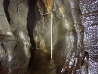
One has to work within the constraints for watercourses inside or approaching caves that nature has provided.  We were lucky enough to find a sheltered spot with deep enough water all year round for the depth guage to be installed, and an unfloodable rock shelf well above it for logger, while 10m further up the same passage was a natural limestone flume for the purpose of doing the maths to convert river depth to flow rate.  We recorded the river depth every hour for a year on a data logger using some pretty cheap home-made gear as this was predominantly a hobby cave science project.  Later on it found a commercial purpose concerning hydroelectric power generation.

https://en.wikipedia.org/wiki/Flume
https://www.openchannelflow.com/blog/the-72-inch-parshall-flume
http://www.fao.org/3/t0848e/t0848e-09.htm

The same technique has been used in another cave in the same valley for the past 5 years or so, the difference being that commercial submersible depth sensors (Druck) were obtained which were built into 3m scaffolding poles bolted upright to the walls of a canyon section of cave passage.  Again there is a high dry spot for the logger and a small pothole in the riverbed to assure a minimum water depth at all times of the year over the sensor element.

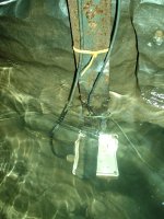
My two photos attached show this scaff pipe arrangement with the ?200 Druck sensor;  also the earlier experiment where a "Ribena plastic drink bag" full of air was submerged in a plastic box on a metal bracket coupled by hardwall PVC tube to a ?20 Honeywell gauge air pressure sensor.  Atmospheric air pressure in both cases is cancelled by the sensors so the measured pressure is due to the water only.

I would suggest a literature search is the next step in Kenilworth's project, plus posting some photos of his candidate cave passage, state its dimensions and gradient to stimulate further ideas.


Attachments

  • DruckSensorInPipe.jpg
    DruckSensorInPipe.jpg
    163 KB · Views: 170
  • WaterDepthAndTemperatureInRiver.jpg
    WaterDepthAndTemperatureInRiver.jpg
    150.1 KB · Views: 170

Pitlamp

Well-known member
MarkS said:
Pitlamp said:
Kenilworth said:
I don't think my stream will float an orange as it's not deep enough. Is there a reason why an orange is favored, and will a smaller, higher riding float do the job?
I honestly don't know Kenilworth - I presume it's something to do with having optimum buoyancy.

My understanding is that it is because they float very low in the water. For measuring flow rates outside it is important to minimise any influence of wind, but depending on the flow rate that might not be so relevant underground.

Yes, reckon you're right Mark. The upthrust is only fractionally greater than the weight.
 

caving_fox

Active member
I'm very far from being a hydrolic fluids specialist. But surely a floating measure is only measuring the surface velocity hindered by turbulence and air drag while the main body of water moves much faster in the center of the bulk? I've no idea how big the difference/error this would be (presumably more for larger streams?) or how it would compare to all the other errors involved.
 

Pitlamp

Well-known member
Fair comment - I'd have thought it was actually moving faster at the surface rather than nearer the sides / bottom of the stream, where frictional forces would slow the flow.

So yes - this method only provides an estimate.
 
Top