[size=14pt]Cave Logger Mk1[/size]
It's been great to see so many people taking an interest in the project and the time to offer useful advice/ideas :bow:
Now I've had some time to consider how to make the cave flood event monitoring device.
I've designed a prototype and come up with a list of attributes I want it to have...
Cave logger attributes
A waterproof ultrasonic or water pressure-based water level logging device for flood event monitoring, ultrasonic sensor range 6m +/- 2cm, pressure sensor range 250m water depth +/- 1cm (depending on how waterproof the housing is), still I need to test the devices before I can comment on how accurate they really are.
Flexible: Many Arduino compatible sensors can be plugged into the logger, multiple sensors can be placed on a single logger.
Easily to assemble: To overcome the tedious and annoying process of wiring the cave logger together I've designed a printed circuit board, simply solder on the components and it's good to go.
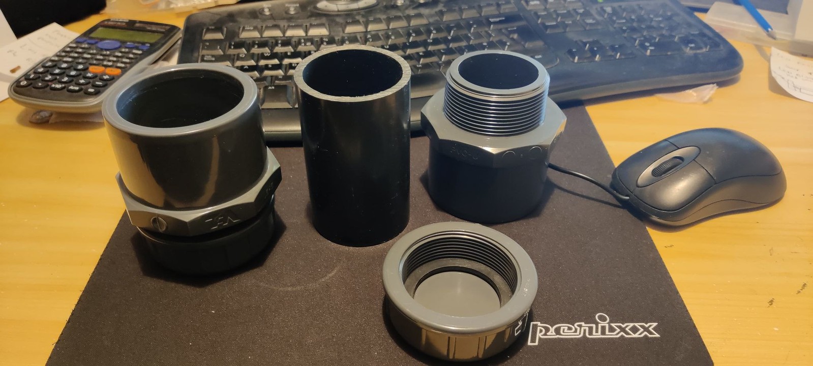
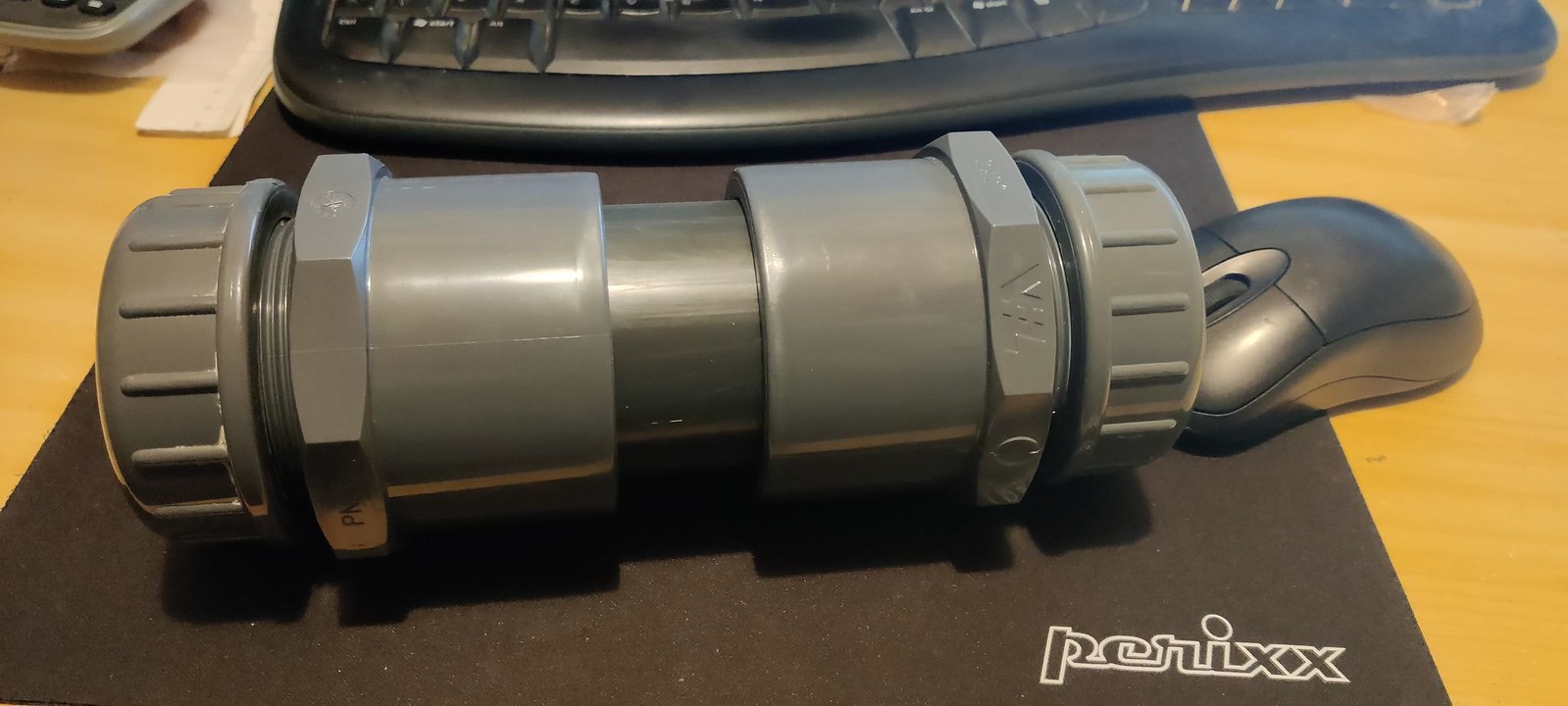
Small: A small device footprint has many advantages, the device is less likely to be noticed by cavers who might try to open it out of curiosity, remove it after mistaking it for rubbish or be offended by its presence. It also means it's easier to carry in and out of the cave. The existing design is a 6" length of grey 2" PVC pipe capped at both ends with plastic welded PVC screw cap fittings.
Cheap: The logger and housing should cost less than ?50 to make, the other additional costs being sensors.
Logger + housing component list
Arduino pro mini: ?2.00
SD card module: ?0.60
RTC module: ?1.00
Display module: ?1.70
TTL adapter (PC interface): ?2.00
3.3V regulator: ?4.00
5V regulator: ?4.00
PCB: ?3.00
battery case: ?1.80
transistors and resistors: ?1.00
SD card: ?2.00
switch: ?0.10
power in: ?0.10
2" PVC pipe section: ?5.00
end cap adapters: ?8.40
screw caps: ?6.60
4xAA batteries: ?4
Total: ?48.30
By keeping costs low I should be able to afford more sensors and gather more data for the project, also means I'm not too heart broken if my devices die.
To save on shipping costs I bought multiple components in bulk, also ordered electronic components from china via snail mail.
The list doesn't include necessary tools and consumables such as glue, solder, soldering iron ect.
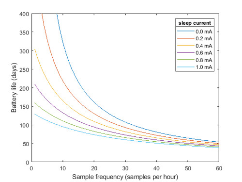
Efficeient: the device almost completely shuts itself down between readings, using less than 1 mA of power when asleep, I can probably improve this further in the next design iteration.
Simple: I'm sure there are many improvements I could make to the device to further improve its efficiency and lower it's cost but in the interest of saving time and my own sanity, I've opted for a more lego based approach where I exploit the efforts of other people. I have designed a device made up of a few cheap and readily available components. Libraries of code already exist and the Arduino IDE makes programming the device very easy.
Rugged: the device housing will be constructed out of thick 10 bar pressure rated 2" PVC piping
https://www.irrigationonline.co.uk/products/PVC-Imperial-Adaptor-Socket-to-Male-Fitting.html.
I'm hoping it will be able to withstand a decent amount of water pressure if submerged. I plan to have sensors sticking out of the housing like this (epoxy glue):
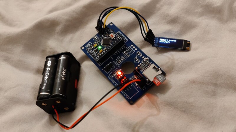
Current progress
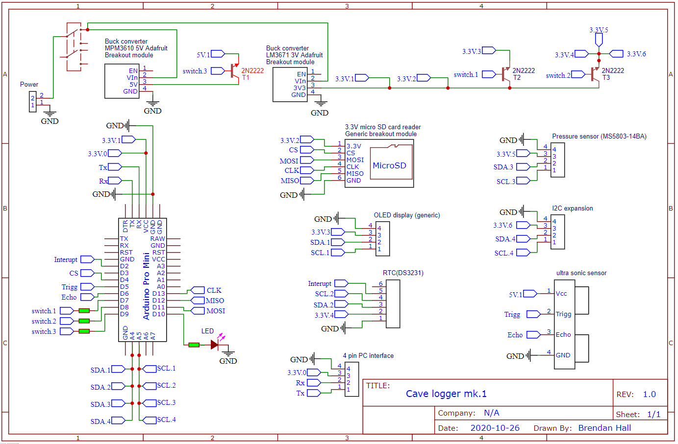
I've finally finished designing the circuit design for the logger, I've sent it off to the PCB print press and it should arrive sometime next week.
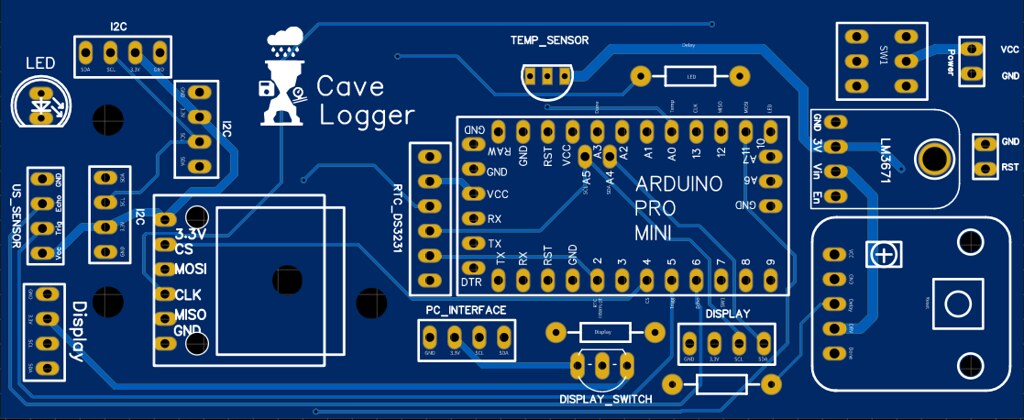
The PCB preview is shown in the image below, component breakdown:
1.
3.3V buck regulator: I plan to use 4 AA batteries as these will fit nicely in a 2" PVC pipe, this step-down regulator turns 5-6V into 3.3V and should be more efficient than a linear regulator as power isn't wasted as heat,
https://cdn-shop.adafruit.com/product-files/2745/P2745_Datasheet.pdf these regulators apparently have a quiescent current draw of 0.16 mA.
2.
5V buck regulator: Same thing again but for 5V, this is for powering an optional 5V ultrasonic sensor, the device will work without this voltage regulator
3.
PC interface: port for a USB serial TTL adapter to interface the device with a PC for programming the Arduino.
4.
Arduino pro mini: a cheap low power microcontroller
5.
LED: pins for optional LED output, can be programmed to let the user know the status of the logger, blinking = recording, constantly on = powered but in an error state. Programmed to turn off after a set period to save power.
6.
OLED display: useful if setting up an ultrasonic based water level sensor, this displays the time/date and data read from the sensor, the display automatically shuts off after a set period to save power.
7/8.
I2C ports: up to two I2C devices can be attached directly to the board, more if you want to wire them on.
9.
Realtime clock (RTC) module: a very accurate temperature regulated realtime clock module for timestamping data.
10.
Transistors and resistors: these are so all of the modules can be turned off when the Arduino is in sleep mode to save power.
11.
SD card module: allows data to be saved to an SD card.
12.
Switch: an optional on/off switch can be placed here.
13.
power pins/screws: leads to a battery pack with 4 AA batteries, I was originally going to use a 3.7V lithium-ion cell but decided it'd be safer to use AA's.
I've made the PCB Gerber files and Arduino code available on GitHub, I used the free PCB software EasyEDA for the circuit board design and ordered the boards from JCBPCB:
https://github.com/blhall195/cave_logger
PCB layout
Circuit design


")